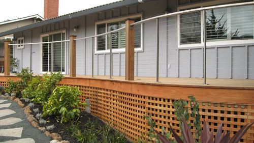
Summer is getting closer, and decks are wonderful places to spend time outdoors. We have built many of them, mostly using redwood or cedar, and sometimes using composite material or hardwood.
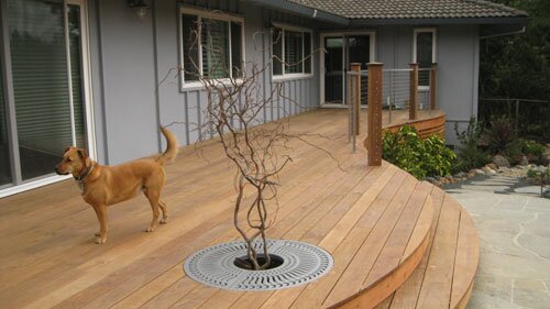
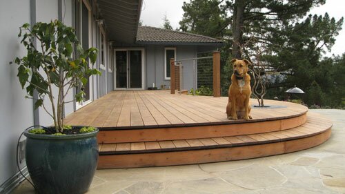
Just a few years ago, we crafted a curved ipe deck that became a true labor of love and one of our flagship projects. The structure underneath was made out of pressure-treated lumber (referred to in the trades as ‘PT’), and the decking material was 5/4″x6″ ipe. This deck is roughly 45 feet long and slightly over 12 feet wide at its widest point.
We will share the sequence of events of this project from start to finish, with as many juicy details as I can dust off, not to mention plenty of photos. Remodel Blog encourages comments and questions, as always.
© CVAN Builders
Deck Design
Our clients had a team of professionals to tackle their project:
- A landscape designer who shaped the deck, flagstone patio, plants and irrigation;
- An architect who prepared drawings as part of the building permit application;
- Structural and soils engineers who provided footing and framing details;
- My company’s crew of carpenters, electricians and plumbers; and
- A landscape contractor

© CVAN Builders
During the deck design phase, the owners were quite busy deciding on many details, including what kind of decking material to use. There are a huge number of composite materials available, but most of them have ugly side effects that do not become visible until later. Fading colors, incompatibility with certain plastics and rubbers (outdoor furniture, plant pots, and garden hoses), mold, and deformation are just a few examples. If you are interested in a composite deck, make sure you do your homework and check it twice.
Ipe Decking
In the end, the clients decided on 5/4” (meaning a full one inch thick) Iron Woods ipe. Iron Woods ipe is a particular ‘brand’ of ipe that received high ratings from Consumer Reports magazine. Also known as Brazilian walnut, this is an extremely dense material, fire-resistant, very heavy, and at times challenging to work with. Ipe requires special preparation and installation methods, and definitely takes more time to install than softwoods such as cedar or redwood.
Deck framing, Lay-out & Elevations
© CVAN Builders
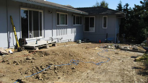
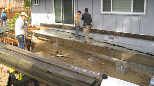
After receiving the building permit, it was time to get to work. The owners had already cleared away old brush and a tree. The first thing we did was to establish elevations with laser levels, lay out the framing structure and related footings. There was an existing foundation from an old deck that had been torn down a long time ago. We wanted our new lay-out to bypass this, so we could simply leave it in the ground rather than wasting time with jackhammers to remove it. The photo below shows several footing excavations, as well as a utility trench in the foreground. We buried a new water line in this one, and electrical and more water lines in another.

© CVAN Builders
Concrete Footings
When considering footings, we don’t recommend the use of so-called ‘pier blocks’ as structural supports. They are not as substantial as steel-reinforced concrete, and lack strength and connectors that improve your deck’s integrity in case of an earthquake. This may not be a problem in your area, but in and around San Francisco we have to take this condition quite seriously.

Used with permission © Andersson Woodrow
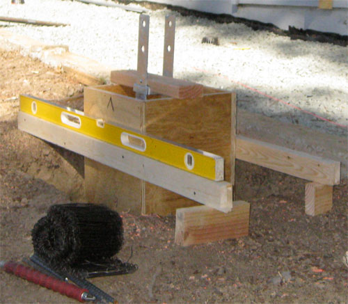
The engineering specs called for 24″x24″x24″ footings. The pedestal of the footings had to be a minimum of 8″ above grade, making them at least 24 inches tall.
When you build forms, make sure you will be able to remove them later. Building inspectors rarely allow wood forms to be left in the ground, nor would you want to.
Consider coating the inside of the forms with form oil. This will make them easier to remove once the concrete has set. Use care not to get oil on rebar, as that will prevent concrete from sticking to the steel.
There also was a specific rebar design; see drawing detail. Generally all rebar and hardware connectors have to be in place prior to inspection. So-called ‘wet-set’ installation — when brackets etc are set at the same time concrete is poured — is generally not allowed. Depending on your specific design, rebar is often required to be connected to whatever hardware that’s called for, and a ‘wet-set’ procedure makes that very difficult if not impossible.
Please keep in mind that this footing spec was created specifically for the location and conditions of our job site. On some projects this design will be overkill, while on others it may be insufficient.
© CVAN Builders
Steel stakes were added later to keep form from moving. There was a fair amount of concrete to be poured, and we decided against trying to mix it onsite. Instead we arranged for a cement truck and a concrete pumping contractor to fill the excavated footings. We like using a vibrator to get rid of any air pockets in the cement. Be careful to not vibrate the cement too long or all the gravel will sink to the bottom.
When calculating how much concrete you will need, add roughly 10% extra to the total you come up with. This is because:
- During excavation the holes often become larger than you intended;
- Sometimes small cave-ins occur, requiring additional concrete;
- A lot of concrete will stay in the pump truck’s hose;
- Concrete is cheap. Why take the risk of coming up short?
There are some handy concrete calculators to be found online, but double-check the math to make sure it’s right. The day after the pour we stripped the forms and started installing 4×12 beams, plus the ledger board that’s bolted against the wall.
Deck Framing
As an aside, we prefer to build decks to be free-standing; i.e., without being physically connected to the house. That’s not always practical, and it means more footings. When a ledger is installed against a house, as it was in this case, make sure you use spacers (see Resources below) between the back of that board and whatever kind of surface it will be bolted against. These spacers greatly reduce the chances of rot and decay. Using galvanized sheet metal (GSM) ‘Z’ flashing that tucks under the siding’s moisture barrier and sits on top of the ledger board is an excellent idea. Use only galvanized thru-bolts (as opposed to lag screws) with beefy washers to attach the ledger board. If your engineer allows lag screws, first drill pilot holes and fill them with silicone-based caulk. This will help prevent moisture from entering the framing. The engineer called for specific blocking, hardware, and methods to fastening the ledger to the existing framing.
© CVAN Builders
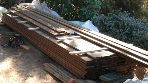
In the meantime, Economy Lumber’s truck showed up with the ipe delivery. We found a place where it would not be in blasting sun each day, and we made sure to use stickers in between each layer. These thin pieces of wood create a space between each layer of boards, allowing air circulation and giving ipe a chance to acclimate. This is an important step, so don’t skip it and allow at least five days for this process.
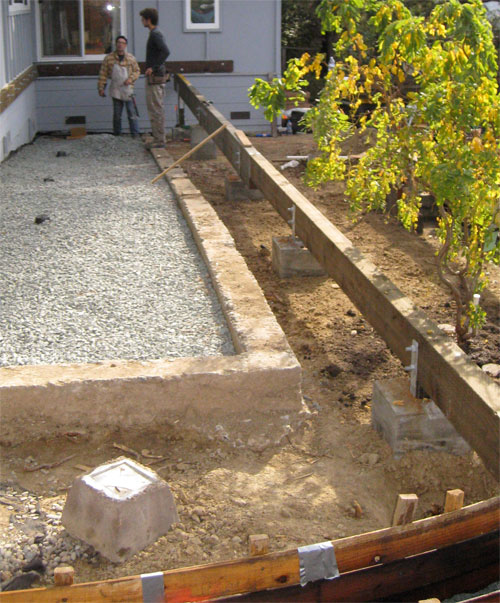
To prevent weeds from growing under the deck, the grade was covered with landscape fabric, followed by about three inches of gravel. A small tree was planned in the deck area, so pipes for irrigation and conduit for lighting were installed before we proceeded with installing deck joists. The owners also had an underground drainage system installed.
Placing Deck Joists
The joists were installed at 16″ OC (on center). Because the ipe boards were a full one inch thick we technically could have installed framing at 24″ OC, but to keep the decking as strong and stable as possible, we opted for a tighter span. Remember that when you frame with PT lumber you must use galvanized nails and hardware. The chemicals used to treat this lumber are quite corrosive, so regular steel would not last long. Remember, too, to treat all cut ends of this lumber with a preservative such as Copper Green. As an aside, not all framing hardware is available as galvanized. In those case we typically create a barrier between the hardware and lumber with a piece of bitumen tape. Details, details…
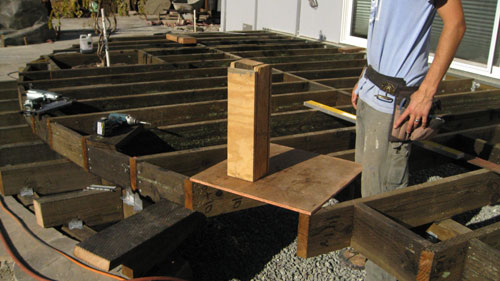
In the photo above, Josh helps to figure out placement of the railing posts. A cable system will be installed between them, and due to huge stress placed on the posts we want to make sure the posts are anchored to the framing as well as possible.
One other thing about PT you should be aware of is that it is sold in different colors using different preservatives. Read more about the fine details here.

To make the framing lumber last as long as possible, we added bitumen tape to the top of the joists, prior to installing the deck boards. Typically the gaps between them collect dirt as time goes by. Then the dirt gets wet during the winter, or when plants are watered or the deck is hosed off, leaving an almost constant humid collection of dirt. Over time this will begin to rot the framing, even the PT kind. Self-sealing bitumen tape, such as Grace Vycor, is relatively inexpensive and easy to apply.
Once all the blocking and joists are in, it is time to call the building inspector and get the framing segment approved and signed off.

Installing Deck Boards
The ends of ipe boards have a tendency to check, so it is recommended to immediately seal every end after it has been cut. We used a gel called AnchorSeal. Initially there were conversations with the client about possibly using a hidden fastener system, but nearly every reputable ipe supplier recommended using face screws at 16” o.c. to prevent cupping. There was not much difficulty with warped or twisted boards, and the usual ‘board bender’ tools worked fine.
Using Stainless Steel Screws For Your Ipe Deck
To keep the boards from cupping, it was widely suggested to use two screws at 16” OC. The clients were not fond of the idea that all those screw heads would remain visible, so they asked that they be covered up with ipe plugs. While we always pre-drill screw holes — even in softwoods — this is doubly important with ipe. We installed over 1,800 stainless steel screws; stainless because this does not interact with the corrosive chemicals found in pressure treated lumber. Of course we also had to counter-sink the screw heads so there would be room for the ipe plugs.
Ipe Plugs
At first we thought about making our own plugs, but ipe is so hard this would probably take days, not to mention we’d burn through countless bits. I found a web site with reasonable prices, and before long a shipment arrived. The next question was how to keep the plugs in place. Nick suggested Titebond 3, applied with a Q-tip to the inside wall of the counter-sunk hole. If applied to the outside of the plug, most glue would get removed while inserting the plug into the board and leave glue on top of the deck board.
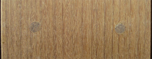
After inserting all 1,803 ipe plugs (I’m mentioning that number only for dramatic effect; it actually went faster than anticipated), we came back the next day with sharp chisels and trimmed all that stuck out above the deck board surface. Later we checked the entire deck and sanded where necessary.
Deck Ventilation
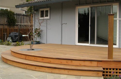
As you’ve probably read or heard, you want good ventilation under your deck. The right side of our deck sits nearly 4 feet above the ground, and with the installation of trellis material, adequate air movement is not an issue. However, on the left side of the deck there’s little room under the step. To encourage air flow, we left a ¾” gap between the bottom of each step and the top of the riser. It looks just like a shadow line and is not as visually obvious as one might think. You can also paint the step or stair framing black to minimize its visibility. A gap was also left between the flagstone and riser mostly to prevent the riser from wicking water, and as an added bonus this gap helps with air circulation as well.
Curved Riser
Clearly ipe is too hard and dense to bend. While I’ve read few articles from carpenters who cut boards to create 1/4″ x 7″ strips that could be bent and glued to 2 additional strips to create a 3/4″ riser, this seemed not easy to do. For one thing, running ipe through a table saw in that manner must’ve left many saw blades smoking! We decided to buy several nearly clear 2x redwood boards, and milled those to the dimensions mentioned above. The first two layers were stapled and glued to the riser framing, and the last layer was glued, clamped, and received a few finish nails at joints. The color of the redwood complements that of the ipe, even when they age.
Railing Posts
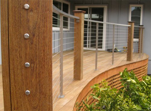
The railing posts were pressured-treated 4x4s bolted as well as possible to joists and blocks. We then covered all four sides with ipe and installed deck boards around them. This looks far better than butting deck boards up against the 4×4 and setting the vertical post wrap boards on top of the deck boards. We used a combination of galvanized finish nails and stainless steel trim head screws to assemble the posts.
Curved Stainless Steel Railing
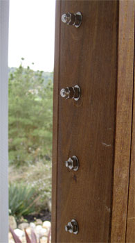
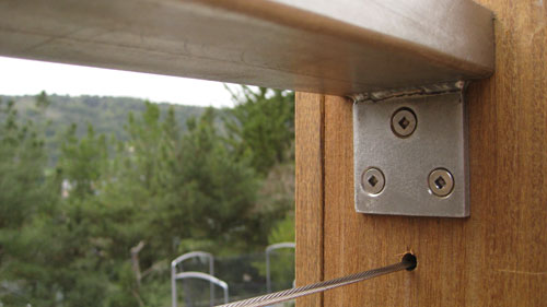
The railing and ‘interim’ steel posts were custom-made. The manufacturer supplied us with a steel template for the holes that had to be drilled in the wood posts. The cables were a challenge. We used a rigid wire to come up with a total length for each cable, and took that to the cable company. They fastened terminators at each end, and supplied us with nuts etc. Because building code requires that spacing can not be less than 4 inches between each cable, they had to be installed very tightly to minimize any slack.
The threaded terminators were located between the first post and the house, leaving very little room for tools and adjustments. Tightening the nuts was not always easy as some of the cables would start turning right along. While it was tempting to put a Vice Grip type of pliers on the cable, it would be easy to damage it. In the end the pliers were installed at the very end of the threaded terminators, taking care to preserve the threads so finish nuts could be installed. Installing these cables was a great opportunity to practice ‘being Zen’ at work!
Resources
- Iron Woods ipe
- Decking materials review by Consumer Reports
- Deck-To-Wall spacers
- Deck construction by CVAN Builders
- Hardscape, landscape, and deck design by Leigh Designs
- Architecture by RS Donahue Architect
- Engineering by Andersson Woodrow, Fairfax, CA
- Special inspection by Dave Olnes PE Inc., Oakland, CA
See also our post on Second Story Deck Construction
Note: This article was first published on April 11, 2012. Due to a malware attack on our servers in 2013, a few posts were lost including this one. As there was no back-up available at that time, we have now reconstructed and republished this article. You may be able to view the original version by visiting the WayBackMachine and entering Remodelblog.net in the search box.
This post, including all text, photographs, and drawing, are protected by U.S. copyright laws. Please ask for permission before using all or parts of this post.
]]>
It is about time we publish a hands-on, how-to, nuts & bolts article. Last week we poured a new concrete slab that is part of a larger remodeling project. The pad was made for a Jacuzzi hot tub that needed to be relocated.
Ready? Here we go…
1. Figure out the dimensions of the slab you need. I like to make a simple drawing to make sure I am not missing anything — see below. (In the bottom right-hand corner the client’s identity was redacted)

(Client info redacted to protect her privacy)
2. Determine precisely where you want it, and keep in mind that most municipalities require a clearance from the property line. This distance can be four feet or more. Check with your local building or planning department. While on that topic, most building departments do not care about so-called flatwork — a different term for concrete pads, driveways, and such, as long as you do not put something underneath, such as plumbing, electrical conduit, and so forth.
3. Figure that the slab should be at least five inches thick. Why? You need at least two inches from the top of the rebar to the top of the slab, and that same distance from the bottom of rebar to the bottom of the slab. The area where two pieces of rebar intersect produces a dimension of one inch, assuming you are using 1/2″ rebar. Plus two to the top and two to the bottom = 2 + 1 + 2 = 5. If you plan to install something very heavy on the slab, or something with a high point load, do yourself a favor and check with an engineer. It is better to spend a few hundred bucks on an expert than far more on a demo crew to take out your concrete.
You may already know about my disdain and distrust of articles written by e-how. They publish info that is often incorrect, in part because many of their so-called ‘contributors’ have zero experience with the topics they write about. Stay far away from these folks — all they want is for you to click on ads.
4. Excavate your site to make room for the forms and slab, and be sure to allow for at least three inches of gravel underneath. Figure out what you will do with the dirt. Can it go elsewhere on the property, or does it have to be hauled away? Is there anything below the surface that you are excavating? In our case there was a lawn sprinkler, so we asked the client’s landscape to disconnect it. Otherwise, if a sprinkler pipe ever needed repair you would not be able to get to it.
Should your excavation be more than 5 or 6 inches, be sure to alert Underground Service Alert before you start work. Read more about them in this earlier post.
5. Once your form is in place (remember to install braces so the form will not fall apart once concrete is poured), compact the gravel with a Whacker compactor or similar. This equipment is heavy, so having a helper on hand is a good idea.

6. Install the necessary rebar, and be sure to use ample 2″ dobies (shown above) to create the necessary clearance between the gravel and the underside of the rebar. Be sure to tie everything together, and please do not use pieces of rock or other loose material that could dislodge during the pour.
7. Figure out how much concrete you will need. There are calculators on the internet that can help you figure this out. When you enter the dimensions, keep in mind that the grade of your location may not be level. At our job site, the yard sloped toward the house, so one side of the pad required more concrete than the opposite side. For example, using the dimension shown in the sketch, the calculator linked to above says I need 0.9 cubic yards. Yet I ordered 1-1/4 cu. yd. and still did not have enough. We happened to have two left-over bags sitting around, and those saved our bacon.
I recommend ordering about ten percent extra. Also consider if you would like to have a color added. Something like ‘lampblack’ yields a slight darker color, which is often nicer than the standard color of cement and it does not cost much. Will you want an accelerant to speed up the drying process?

8. Depending on the size and location of your project, you can either carry the concrete by wheelbarrow from the deliver truck to the site, or you can hire a pump truck which uses hoses to pump the cement from the truck to your project. An so-called gondola can also be used. Given that this was a small project, concrete went straight from the truck in a wheelbarrow. Concrete companies usually include a brief standby time in their charges to allow for this. Apply form oil to the inside of the form material to help concrete not stick to it. Be sure to not get this oil on the rebar.
9. Once the pour is complete, used a screed to level the concrete from side-to-side. Then use a wide float attached to a pole to smooth out the surface. Let it sit for awile so it can start to set. Then with hand-held float start the finish, round over the edges, and so forth. The final finish can be a ‘broom’ finish or a trowel finish. Depending on what you intend to use the slab for, many other finishes are available.
10. Remove the forms, finish the sides of the concrete pad if necessary, and you are good to go!

In our particular case, we installed 3/4 inch rigid electrical conduit underneath, had it inspected by the local building inspector, and then did the pour. You can see the conduit stubbed out of the pad; it has black electrician’s tape at the top of it. The disconnect for the tub was installed in the right rear of the tub in the photo below (not shown). Be sure to check the National Electrical Code, as there are specific distance and line-of-sight requirements.


You would want one, too, if you lived in Sausalito with a beautiful view of the San Francisco Bay. A stroke of luck for my company, several other builders were not willing to deal with steel deck supports. True, steel is far less forgiving than wood, yet that made this an interesting challenge. And who would not love having a job with a view like that?
The reason this 2nd floor deck received steel posts is to keep the view from downstairs windows relatively unobstructed, and to maintain usability of the flagstone porch. Sausalito is located in earthquake country, and had the deck been designed using wood posts, it would necessarily have included an X-shaped brace between them to resist lateral movement. As you can tell from the photo below, this would have impeded the view substantially.

Just so you have an overview of this second story project, we:
- Removed the stairs and garden shed below;
- Replaced the master bedroom window (top left);
- Replaced the bedroom door with a new Marvin door;
- Added a new Marvin door to right of door shown, into the kitchen; and
- Kept the opening at the bottom of the stairs, but filled-in the lower half with a railing.
Preparing For Construction
The owners already had construction drawings made by an engineering firm, so all that was left was to obtain a building permit and get to work.
The single most important preparation was figuring out the height of the tube steel posts, just over 14 feet. This was determined by putting a laser level on the finished floor of the 2nd story master bedroom, and projecting the laser beam at a grade rod, placed on the patio where each support post would be located. The reason this measurement had all of our attention is obvious: if a wooden support is a bit too tall, it can easily be cut. If it’s too short, shimming is always an option. With steel, however, adjustments are a bit more tricky. Once we were satisfied with our work, we verified placement of the posts, and called-in the cavalry.
Pier Drilling
The engineer had established that each pier should be 12 inches in diameter, and about 7 feet deep. They ended up a little deeper than that, based on soil inspections while drilling took place.
Tip:
If your project includes drilling or excavating of any kind, remember to:
- Call 811 or visit Underground Service Alert if your project is located in California. At no charge to you, these friendly folks notify local utility companies who will come out in a jiffy to mark most utilities that may be underground. If you do not call and cause damage, you will be held responsible for repair costs.
- Have plenty of thick plywood around to securely cover any pier holes or other excavations. It is easy for a child or pet to fall into.
- Consider what to do with all that dirt. Where will it go? Can you spread it out around your property? Do you know of someone who needs dirt? Having it hauled away is expensive.

Another Tip:
I highly recommend you insert a sleeve akin to Sonotube to protect your newly drilled holes from caving in. If they do, you can pretty much start all over again, and who wants that?
Lastly, remember that the hydraulic drill rig is powered by a tow-behind compressor. See to it that you have adequate parking space, and make sure there is sufficient clearance for ambulances and fire trucks to pass by. Typically ‘No Parking‘ signs can be obtained from the same authority that issued your building permit. One of our projects required that an entire street be closed to through-traffic. We had to obtain special permits, install road signs days ahead of time, and have extra personnel on hand to re-route traffic.


Photo was taken at different job site, but same hydraulic drill rig was used in Sausalito
Rebar Cages
Once the holes are drilled, you are ready to install rebar cages. Here’s a photo of one used on a different project. This baby is a nearly eleven feet long, as compared to the 7+ feet we used for the 2nd story deck. The latter had a coil design, unlike the one shown.

When rebar is installed right next to dirt, there needs to be a 3 inch space between the two. We ended up tying a bunch of 3″ so-called dobies to the outside of the cage. This helped center the it as we lowered into the freshly drilled holes. (A dobie is a square chunk of cement, measuring 3x3x3 inches in this case. It also has two pieces of tie wire sticking out, so it can be attached to rebar). When determining the diameter of the hole to be drilled, figure as follows: take the engineer’s spec (16″ in our case), then deduct a 3″ clearance on each side of the cage, so the actual cage diameter is 16 minus (2×3) 6= 10″. That 3 inch clearance also applies to the bottom of the cage. Unless you want the whole thing to rust out in a few years, take these clearances seriously and install with care.
If you want to do things fancy, you could have the rebar cages coated to prevent rust. I often see these coatings on CalTrans projects. Anyone in northern California knows where to get this done? I’d be interested. As an aside, here are photos of a huge rebar cage being lowered by a crane, and of note are guiding wheels welded to the outside of the cage. They help center the entire unit while being inserted into the hole. Cool!


Setting J Bolts And Pouring Concrete
As the name implies, J-bolts are bolts shaped like the letter J. The hook at the bottom provides good protection against uplifting motion. These bolts are supposed to be tied to the rebar cage with tie wire, and this entire contraption should be rigid so it won’t move during the concrete pour. Easier said than done. Sure, there are many ways to rig up some lateral supports, but we were faced with another obstacle. One of the pier holes was taking on water, and I really didn’t want to see that.

A garden hose was guided to the bottom of the pier, and connected to a transfer pump. That was all fine and good, but there just wasn’t enough room for the hose plus the cage plus a rig that would keep the j-bolts steady, plus room for the concrete pumping hose. On top of that we also wanted to stick in a vibrator during the pour. All this had to be in place for the building inspector to see, hence my concern. In the end, the J-bolts rig was not secured, and the inspector was grumpy but yet he did not interfere. CVAN Builders did several projects in Sausalito back-to-back, and received many compliments from the local building official. Good relationships with inspectors go a long way. A lonnggg way!
How Much Concrete? What Kind?
There are many calculators on the internet for just this purpose. Once you know how many yards of concrete you will need, add about 10% to what you calculated. The reasons are that:
- When an auger pulls dirt from a hole, it tends to scrape additional dirt off the hole wall, thus requiring more concrete to fill; and
- Once piers are drilled and soil is removed, dirt begins to dry and shrink. This is a minor issue, but some holes do linger due to inspection delays, and so forth.
When you order concrete, you will be asked about the size of rock, slump, sack mix, and PSI. It is outside the scope of this post to delve into these, but gaining familiarity will help you.
Using a concrete vibrator helps eliminate air bubbles, and provides greater density. Don’t keep this tool in one place too long, or you risk gravel sinking to the bottom, and thus decreasing pier strength. Dang! One more… be sure to wrap the threaded part of the J-bolts with duct tape before concrete is poured. The threads will stay clean, making it so much easier to install the nuts.
Oh, before I forget: in many cases you’ll use a subcontractor who provides the concrete pump and hoses. When your pour is done and they get ready to clean up, what will happen to the concrete that’s inside the hoses? For a marginal charge, the left-overs can be pumped back into the concrete truck, and the manufacturer will recycle it. Just remember to add this to your budget.
Lastly, you may be required by the building department to have so-called ‘special inspections’. This means that either the original engineer, or, and more likely, an independent engineer, be present during the pour. He will verify that the work was done according to the construction drawings, and his lab may test the concrete to verify it meets the required strength. Your local building department may also require an ‘observation letter’, signed and stamped by the independent engineer. Special inspections and observation letters can easily add $1,000 or more to your project, so keep it in mind. when making your budget. An independent engineer (aka testing engineer) can be hired only by the client, not by the contractor or architect. This is to prevent any conflict of interest.
Installing Tube Steel Posts
While all the other work was underway, our steel contractor was putting together the posts. He left the base plates for last, so we could make precise measurements of the j-bolt locations after they were installed. A little tweaking of these is possible, but take great care in doing so. The last thing you want to do is compromise structural integrity.

Keep in mind, too, that you will want room for a ratchet or wrench, and you will want the bottom of the nuts to fasten flat agains the top of the base plate. In addition, this plate has welds that attach it to the tube steel, and this takes up some space. I admit I forgot about that until it was pointed out to me; it pays to have great subcontractors. First install nuts that will go below the base plate. Level them out as well as you possible can. Next install the posts, and take care to not bur threads or bend j-bolts. Once in place, fasten the top nuts, hand-tight, and put a 6 foot level along each post. Once you’re good in all directions, tighten all nuts, and fill the space below the base plate with epoxy grout.

Deck Framing
We installed a 6×10 header between the posts. It was made of pressure-treated fir, and since the post buckets were not galvanized steel, we used bitumen tape instead. As long as you install a long-lasting barrier between steel and pressure-treated lumber, you’re good to go. Perpendicular to this beam, we installed a 3x ledger that was attached to the house. Similar to the project I described in ‘Curved Ipe Deck — Photos & Tips‘, we installed deck-to-house spacers to create a break between ledger and siding. All holes into the house framing were pre-drilled and filled with silicone caulk prior to installing galvanized lag screws.
I can quickly think of several scenarios in which a ledger would be attached straight to wall framing, without any deck-to-house spacers. In such cases, order up some GSM flashing. Have it run at least 4 inches up the studs so the wall’s vapor barrier (aka ‘building paper’ will cover it.

One Simpson Tension Tie at each end of the ledger were bolted through the ledger and new blocking in the wall framing with a piece of 5/8″ all-thread, with washer and nuts at each end. After that, framing was conventional. Two-by-six pressure-treated joists fastened with LUS26Z joist hangers (‘Z’ denotes being galvanized). Decking and railing material were all clear heart redwood, which the client unfortunately decided to paint.

Clearances
Deck railings have to be 42 inches high, which can wreak havoc on a nice view once you’re seated at a table. One way around that is to install a cable railing or glass panels. Call your local building department to see if they are allowed. Spindles under the deck railing have to be spaced less than 4 inches apart. For that matter, all spaces that are part of the deck have to adhere to this requirement. Just so little kids don’t get their heads stuck or squeeze through.

Exterior Electrical Receptacle
If you build a deck on a first floor, code requires an electrical receptacle. It should be a GFCI-protected unit, enclosed in appropriate housing. However, on a second story this does not apply. Or so the inspector told us. Call your local building department to make sure they are in agreement.

Hopefully this was of help to you. As always, don’t hesitate to ask questions, no matter how simple. There are other deck projects I want to share, so subscribe to the RSS feed.
Resources
- Deck construction: CVAN Builders
- Design and engineering: Pheif Engineering
- Structural steel: Marin Manufacturing, San Rafael, CA
- Special inspections: Columbia Research & Testing, Windsor, CA

A long time ago, I heard about a product called Dexpan. Made by Archer USA, it is a controlled demolition agent used to break stone and reinforced concrete without the mess, noise, and hazards of conventional demolition tools or explosives. My company typically calls a subcontractor to handle larger concrete demo projects, so I never had a chance to try this stuff. Until a few months ago!
A client in Kensington, CA, for whom we were repairing a leaking roof deck, had an old piece of concrete retaining wall sticking out of the ground. It no longer served any structural purpose, so she asked if we could get rid of it. Electric and pneumatic demo hammers work great on foundations, slabs, and other horizontal surfaces, but using them on anything vertical is a pain in the you-know-what. Figuring this was a perfect opportunity to try Dexpan, two containers of it showed up at the job site a few days later.
We used the Bosch 11241 EVS to drill a series of angled holes in the footing and wall, careful not to drill all the way through. Instructions recommend 1-1/2″ diameter holes, but the largest carbide-tipped drill bit we have is 1-1/4″ and we decided to make do. The holes were spaced about 8″ apart and an equal distance from all edges. You have to make sure there is room for the concrete to expand. If it butts up tightly against a structure you want to preserve, a product like Dexpan is not suitable. After the holes were drilled and cleaned, we mixed the Dexpan powder with water as recommended, and poured it in. I wish we had had a funnel on hand to make the pouring a little easier, and I suggest you get one for your project. Next day we were pleasantly surprised to see the results. Check out this quick vid!
If you have used Dexpan (or a similar product) on a recent project, please share the specifics and how it worked out for you.
]]>